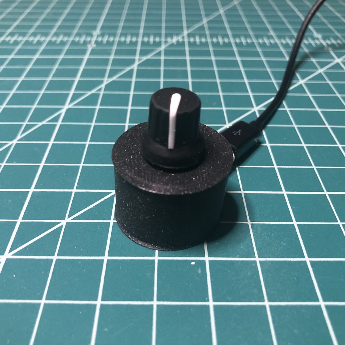
I have plans to build a multi-function macro keyboard using the new Raspberry Pi Pico RP2040 microcontroller and CircuitPython. While I was waiting for it to arrive, I wanted to figure out how I was going to handle controlling the audio on my computer with a rotary encoder, so I built this simple project using CircuitPython and the QT Py M0 microcontroller. Unfortunately, rotaryio has not been implemented for the RP2040 yet in CircuitPython, so there is a bonus code snippet at the end using a potentiometer to accomplish the same thing for the Pi Pico.
Parts
- Adafruit QT Py – SAMD21 Dev Board with STEMMA QT or Seeeduino XIAO – Arduino Microcontroller – SAMD21 Cortex M0+
- Rotary Encoder + Extras
- Silicone Cover Stranded-Core Wire 26AWG
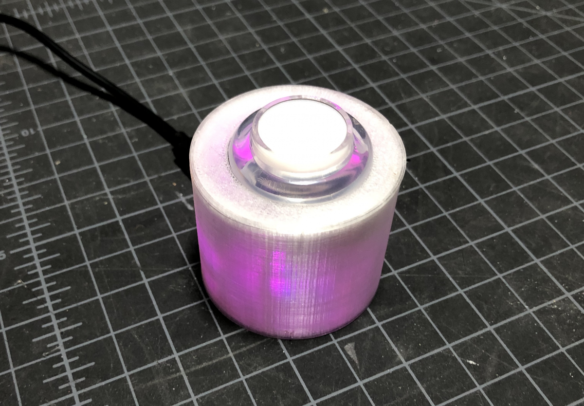
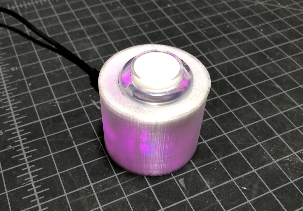
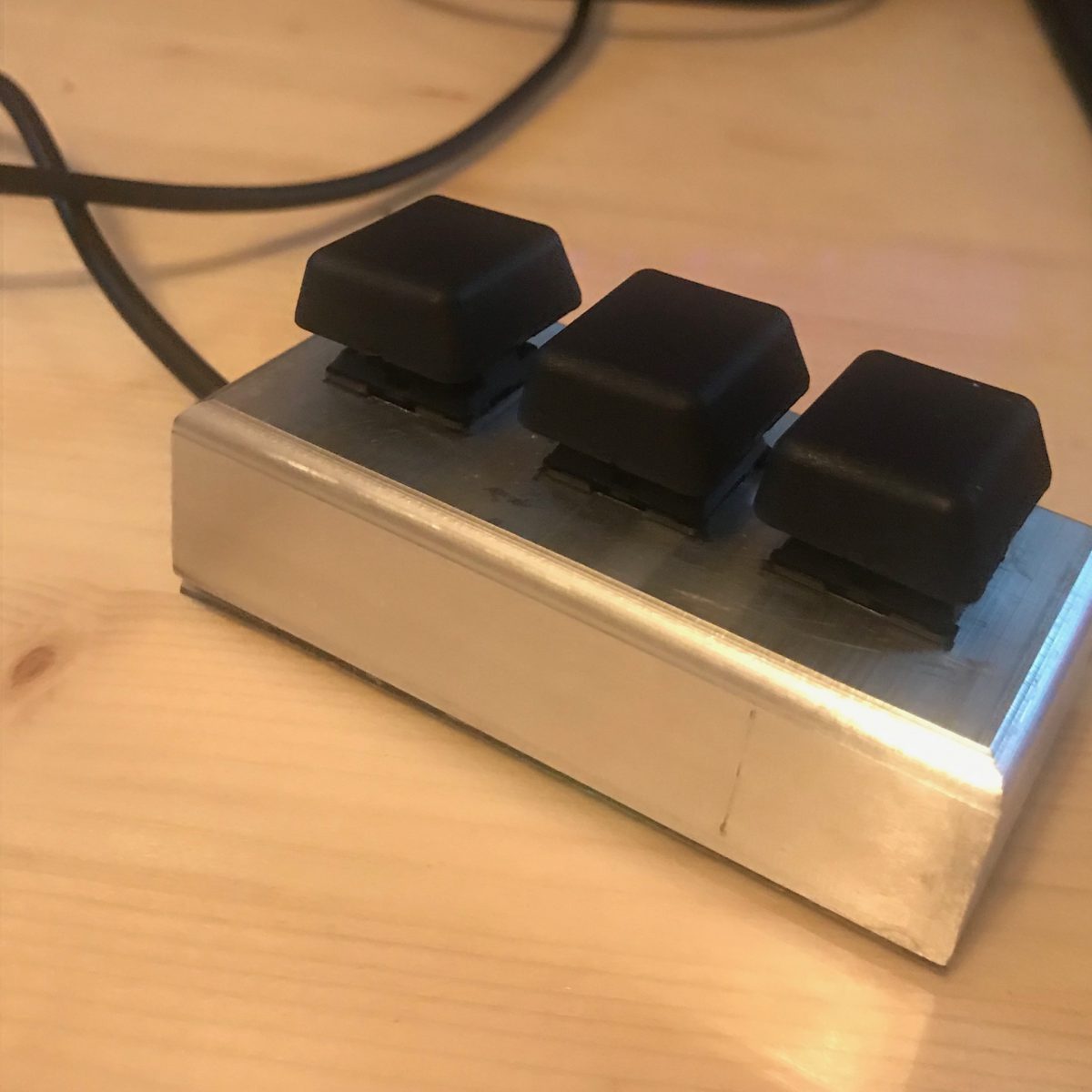
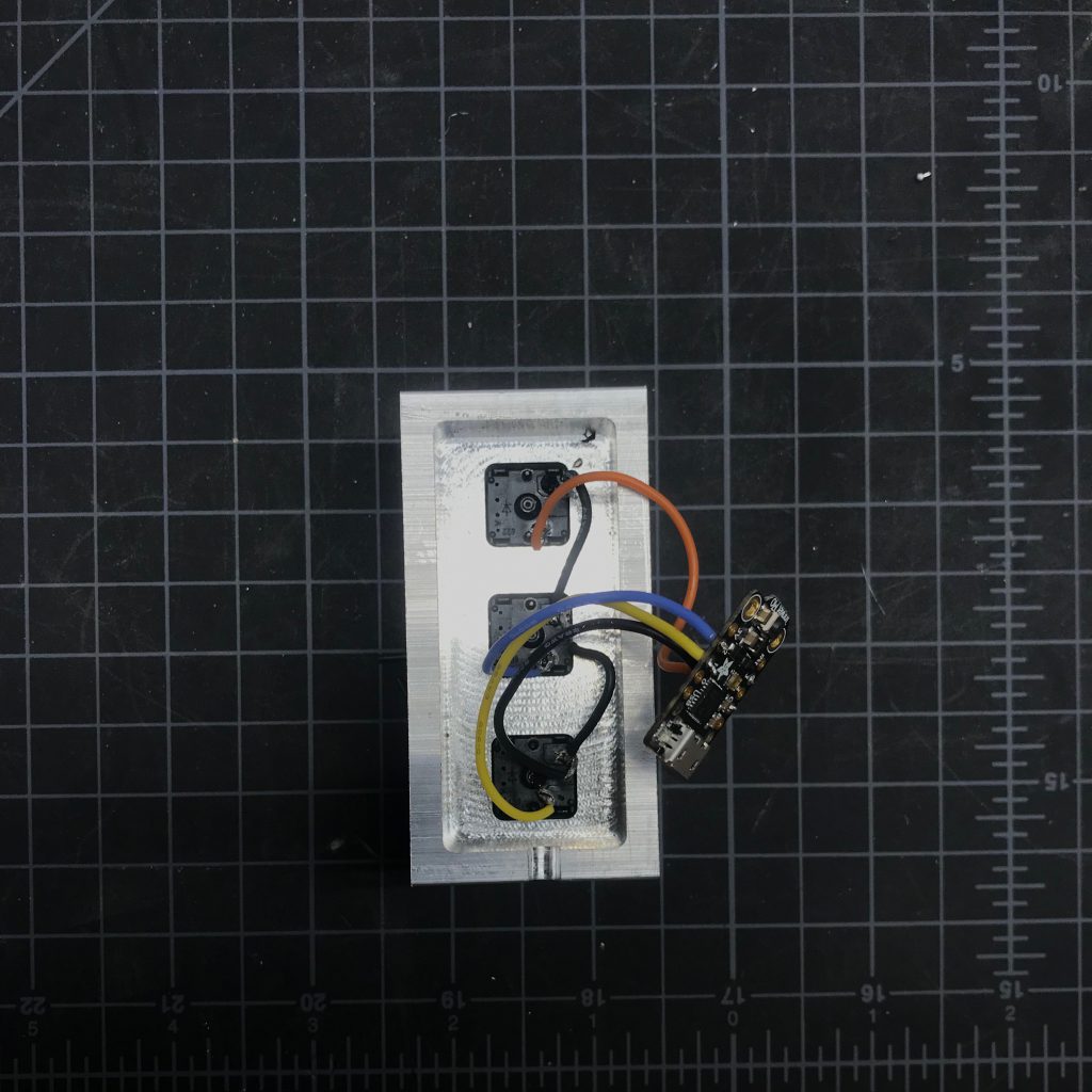
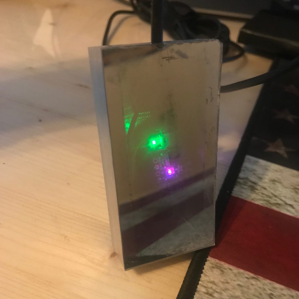
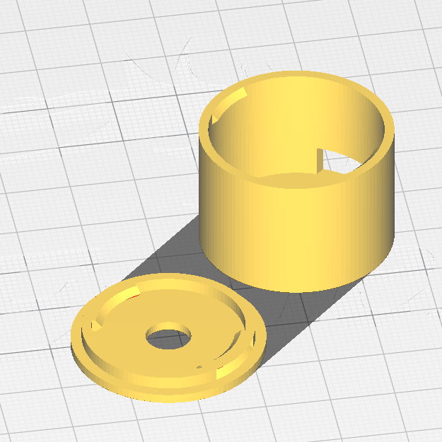
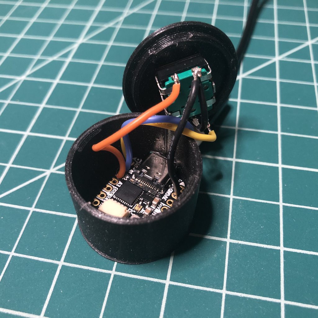
3D Printed SnapFit Enclosure
I modified the enclosure I made for my Zoom/Teams mute button and computer lock button projects.
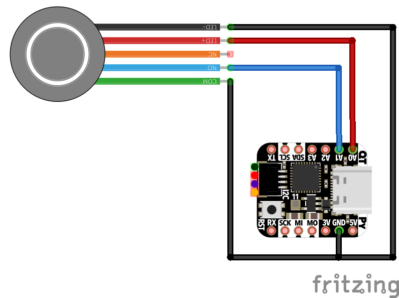
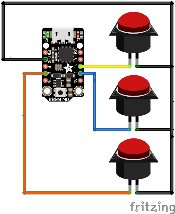
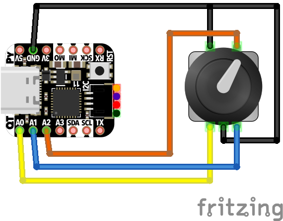
Wiring Diagram

Code
The code.py file is also available on GitHub.
import board
import time
import usb_hid
from digitalio import DigitalInOut, Direction, Pull
from rotaryio import IncrementalEncoder
from adafruit_hid.consumer_control_code import ConsumerControlCode
from adafruit_hid.consumer_control import ConsumerControl

# Change the below code for different outcomes
# https://circuitpython.readthedocs.io/projects/hid/en/latest/

# Button Press will mute
BUTTON_CODE = ConsumerControlCode.MUTE

# Rotating the encoder clockwise will increase the volume
INCREMENT_CODE = ConsumerControlCode.VOLUME_INCREMENT

# Rotating the encoder clockwise will decrease teh volume
DECREMENT_CODE = ConsumerControlCode.VOLUME_DECREMENT

# initialize as hid device
consumer_control = ConsumerControl(usb_hid.devices)

# initialize encoder on pins D0 and D1 (QT Py M0)
encoder = IncrementalEncoder(board.D0, board.D1)

# initialize encoder click on pin D2 (QT Py M0)
button = DigitalInOut(board.D2)
button.direction = Direction.INPUT
button.pull = Pull.UP

button_in = False
last_position = None

while True:

    if not button.value and not button_in:
        print("button press")
        button_in = True
        consumer_control.send(BUTTON_CODE)
        time.sleep(.2)

    elif button.value and button_in:
        button_in = False

    elif button.value and not button_in:
        position = encoder.position

        if last_position is not None and position != last_position:

            if position > last_position:
                print("rotate clockwise")
                consumer_control.send(INCREMENT_CODE)

            elif position < last_position:
                print("rotate counter-clockwise")
                consumer_control.send(DECREMENT_CODE)

        last_position = position
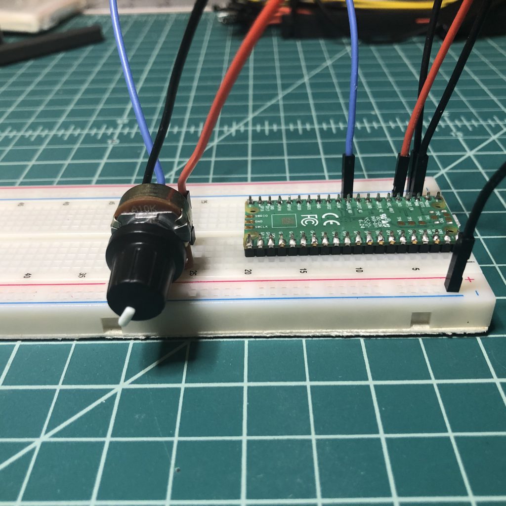
Bonus: Pi Pico 2040 Potentiometer
import board
import time
import usb_hid
from analogio import AnalogIn
from adafruit_hid.consumer_control_code import ConsumerControlCode
from adafruit_hid.consumer_control import ConsumerControl

READ_TIME = .001

def map_function(x, in_min, in_max, out_min, out_max):

  return (x - in_min) * (out_max - out_min) / (in_max - in_min) + out_min;


# initialize hid device as consumer control
consumer_control = ConsumerControl(usb_hid.devices)

# initialize potentiometer (pot) wiper connected to GP26_A0
potentiometer = AnalogIn(board.GP26)

# intialize the read time
last_read = time.monotonic()

# decrease volume all the way down
# this allows the volume to be set by the current value of the pot
for i in range(32):
    consumer_control.send(ConsumerControlCode.VOLUME_DECREMENT)


# initalize volume and last position
current_volume = 0
last_position = 0


while True:

    if time.monotonic() - last_read > READ_TIME:
        position = int(map_function(potentiometer.value , 200, 65520, 0, 32))

        if abs(position - last_position) > 1:

            last_position = position

            if current_volume < position:
                while current_volume < position:
                    # Raise volume.
                    print("Volume Up!")
                    consumer_control.send(ConsumerControlCode.VOLUME_INCREMENT)
                    current_volume+= 2
            elif current_volume > position:
                while current_volume > position:
                    # Lower volume.
                    print("Volume Down!")
                    consumer_control.send(ConsumerControlCode.VOLUME_DECREMENT)
                    current_volume -= 2

        # update last_read to current time
        last_read = time.monotonic()

    # handle time.monotonic() overflow
    if time.monotonic() < last_read:
        last_read = time.monotonic()