Simple USB Audio Controller in CircuitPython

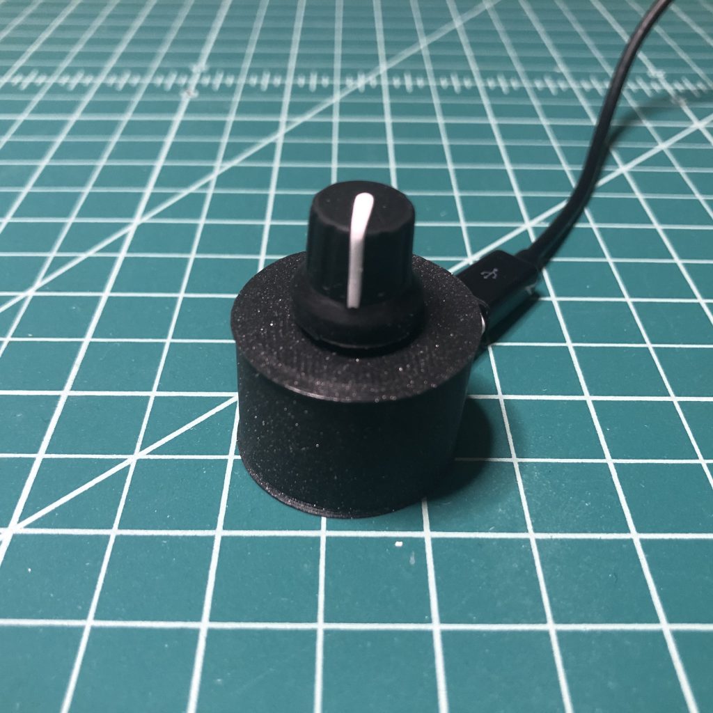
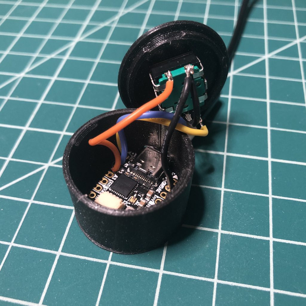
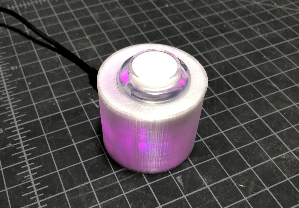
I have plans to build a multi-function macro keyboard using the new Raspberry Pi Pico RP2040 microcontroller and CircuitPython. While I was waiting for it to arrive, I wanted to figure out how I was going to handle controlling the audio on my computer with a rotary encoder, so I built this simple project using CircuitPython and the QT Py M0 microcontroller. Unfortunately, rotaryio has not been implemented for the RP2040 yet in CircuitPython, so there is a bonus code snippet at the end using a potentiometer to accomplish the same thing for the Pi Pico.

Parts

3D Printed SnapFit Enclosure

I modified the enclosure I made for my Zoom/Teams mute button and computer lock button projects.
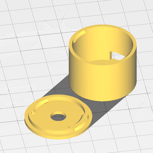
CAD files for the QT Py rotary encoder enclosure.

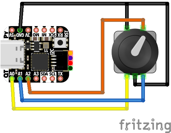
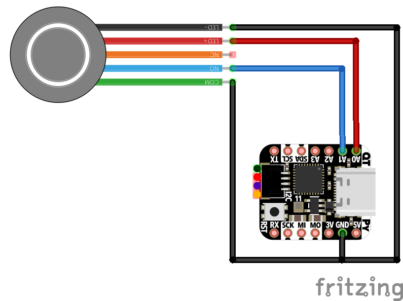
Wiring Diagram

wiring diagram for the QT Py and rotary encoder

Code

The code.py file is also available on GitHub.

import board
import time
import usb_hid
from digitalio import DigitalInOut, Direction, Pull
from rotaryio import IncrementalEncoder
from adafruit_hid.consumer_control_code import ConsumerControlCode
from adafruit_hid.consumer_control import ConsumerControl

# Change the below code for different outcomes
# https://circuitpython.readthedocs.io/projects/hid/en/latest/

# Button Press will mute
BUTTON_CODE = ConsumerControlCode.MUTE

# Rotating the encoder clockwise will increase the volume
INCREMENT_CODE = ConsumerControlCode.VOLUME_INCREMENT

# Rotating the encoder clockwise will decrease teh volume
DECREMENT_CODE = ConsumerControlCode.VOLUME_DECREMENT

# initialize as hid device
consumer_control = ConsumerControl(usb_hid.devices)

# initialize encoder on pins D0 and D1 (QT Py M0)
encoder = IncrementalEncoder(board.D0, board.D1)

# initialize encoder click on pin D2 (QT Py M0)
button = DigitalInOut(board.D2)
button.direction = Direction.INPUT
button.pull = Pull.UP

button_in = False
last_position = None

while True:

    if not button.value and not button_in:
        print("button press")
        button_in = True
        consumer_control.send(BUTTON_CODE)
        time.sleep(.2)

    elif button.value and button_in:
        button_in = False

    elif button.value and not button_in:
        position = encoder.position

        if last_position is not None and position != last_position:

            if position > last_position:
                print("rotate clockwise")
                consumer_control.send(INCREMENT_CODE)

            elif position < last_position:
                print("rotate counter-clockwise")
                consumer_control.send(DECREMENT_CODE)

        last_position = position

Bonus: Pi Pico 2040 Potentiometer
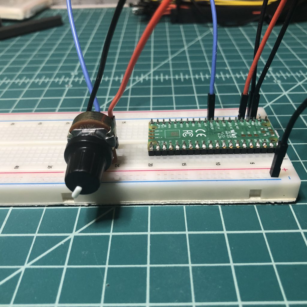
Raspberry Pi Pico 2040 with potentiometer
import board
import time
import usb_hid
from analogio import AnalogIn
from adafruit_hid.consumer_control_code import ConsumerControlCode
from adafruit_hid.consumer_control import ConsumerControl

READ_TIME = .001

def map_function(x, in_min, in_max, out_min, out_max):

  return (x - in_min) * (out_max - out_min) / (in_max - in_min) + out_min;


# initialize hid device as consumer control 
consumer_control = ConsumerControl(usb_hid.devices)

# initialize potentiometer (pot) wiper connected to GP26_A0
potentiometer = AnalogIn(board.GP26)  

# intialize the read time
last_read = time.monotonic()

# decrease volume all the way down 
# this allows the volume to be set by the current value of the pot
for i in range(32):
    consumer_control.send(ConsumerControlCode.VOLUME_DECREMENT)


# initalize volume and last position
current_volume = 0
last_position = 0


while True:

    if time.monotonic() - last_read > READ_TIME:
        position = int(map_function(potentiometer.value , 200, 65520, 0, 32))

        if abs(position - last_position) > 1:

            last_position = position

            if current_volume < position:
                while current_volume < position:
                    # Raise volume.
                    print("Volume Up!")
                    consumer_control.send(ConsumerControlCode.VOLUME_INCREMENT)
                    current_volume+= 2
            elif current_volume > position:
                while current_volume > position:
                    # Lower volume.
                    print("Volume Down!")
                    consumer_control.send(ConsumerControlCode.VOLUME_DECREMENT)
                    current_volume -= 2

        # update last_read to current time
        last_read = time.monotonic()

    # handle time.monotonic() overflow
    if time.monotonic() < last_read:
        last_read = time.monotonic()
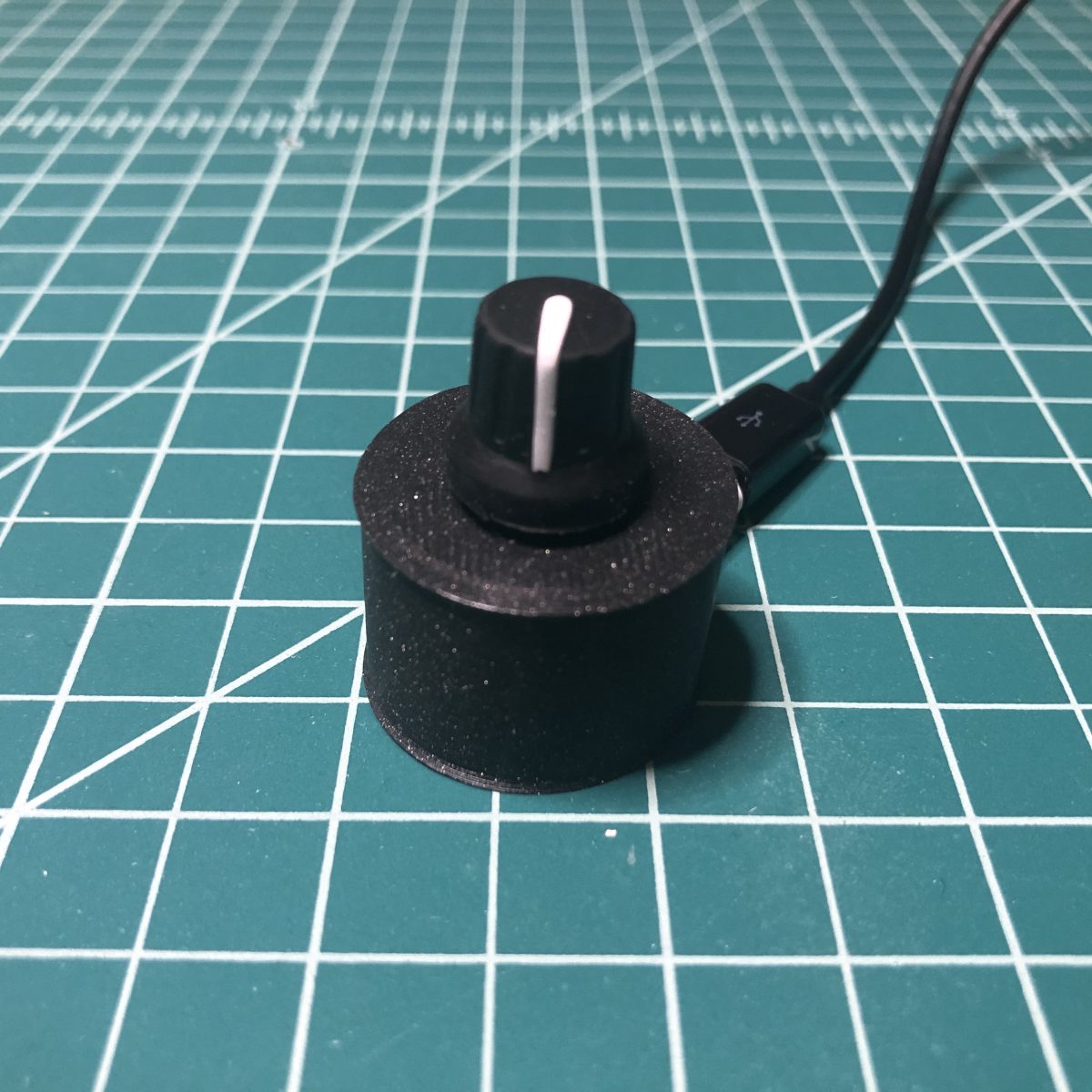
Zoom/Microsoft Teams Mute Button using CircuitPython

I wanted to create a simple project using Adafruit’s new QT Py microcontroller and CircuitPython. I decided to make a simple mute button for video conference tools since I spend a lot of my work hours in meetings using either Microsoft Teams or Zoom. There have been many of these made since the start of the pandemic, including the PyRuler version featured in an Adafruit learn guide, but I wanted to make a smaller single button version that could work with multiple applications.

Parts

3D Printed SnapFit Enclosure

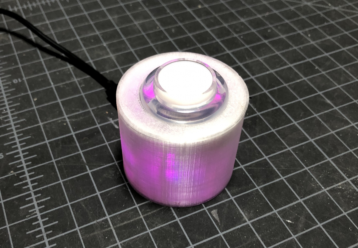
I followed Noé Ruiz (@ecken) Layer by Layer tutorial below to make a circular SnapFit case to hold my project (STL/Fusion360 Files). There are several things that could be improved in this design, but it is a start. The Fusion360 file has User Parameters if you want to change the diameter or the height of the enclosure. I printed my enclosure using semi transparent PETG to enable the user to easily see the color of the onboard neopixle. This is helpful for knowing what application/shortcut is active.

Wiring

The fritzing schematic is below. Please note that the button I used didn’t have a NC connector, but I couldn’t find a similar part in the fritzing library.

Code

Below is the code for this project. Modify the controller_buttons variable to add or remove applications and shortcuts. The current code is made to work using Microsoft Teams and Zoom on a Mac. The keycode for each application/shortcut would need to be modified if you are using Windows or Linux. The color updates the neopixle on the QT Py to allow the user to know which application/shortcut is active. I used purple for Teams and blue for zoom.

https://gist.github.com/jfurcean/b2834bc05f5599a23253b392075b390d

Please see Adafruit’s Primary Guide for setting up the QT Py with CircuitPython. You will need to copy the following CircuitPython library files over to your QT Py as well.

  • adafruit_hid/keyboard
  • adafruit_hid/keyboard_layout_us
  • adafruit_hid/keycode
  • neopixel

The strip_xattr.sh script is very helpful if you run into problems copying the required library files over to the QT Py on a Mac. For more information about this issue see the Adafruit Forum post from user aaaidan.

Use

  1. Plug it into your computer.
  2. Press the button to activate the active application’s keyboard shortcut
  3. In order to change the keyboard shortcut that is active, hold down the button until the onboard neopixel changes colors

Please note that the led on the arcade button is currently set to toggle every time it is pressed. It is up to the user to manually sync it to there current application if they want to use it as an indicator if they are currently muted or not. Comment out the every line that has button_led if you want to use a button that doesn’t have an LED on it. Also, the Teams or Zoom windows has to be in focus for the button to work.

All code and 3D models are available via the Github Repository: https://github.com/jfurcean/CircuitPython-MuteButton

Special Note About Cura

I noticed that my QT Py was constantly resetting/not working while I was working on this project. It turns out that Cura was trying to “talk” to the QT Py and this was preventing it from working. Everything worked as expected once I closed Cura and reset the QT Py. I found this Github issue related to other CircuitPython boards that were having this same issue.

Installing OctoPi-TFT using the OctoPi Image

This tutorial uses vi to edit files this can be replaced with nano or some other text editor.

Parts

Step 1: Connect the PiTFT to the Pi

You can connect the PiTFT before you start any of the other steps.

Step 2: Install and Configure OctoPrint

Follow the instructions form the OctoPrint website https://octoprint.org/download/

Step 3: Install Raspbian Desktop

sudo /home/pi/scripts/install-desktop

sudo reboot

Step 4: Install Dependencies

sudo apt-get install xinit
sudo apt-get install x11-xserver-utils
sudo apt-get install xserver-xorg-input-evdev

Step 5: Move 40-libinput.conf

sudo mv /usr/share/X11/xorg.conf.d/40-libinput.conf ~/

Step 6: Install PiTFT Drivers

Use the Easy Install method that Adafruit supplies

We’ve created a custom kernel package based of off Notro’s awesome framebuffer work, so you can install it over your existing Raspbian (or derivative) images in just a few commands. Our tutorial shows you how to install the software, as well as calibrate the touchscreen, display images such as from your PiCam and more!

Adafruit
cd ~
wget https://raw.githubusercontent.com/adafruit/Raspberry-Pi-Installer-Scripts/master/adafruit-pitft.sh
chmod +x adafruit-pitft.sh
sudo ./adafruit-pitft.sh
  • For the 3.5″ PiTFT select #4
  • If you want the HDMI port on top like I do select #3
  • Would you like the console to appear on the PiTFT display? No
  • Would you like the HDMI display to mirror to the PiTFT display? Yes

Step 7: Uninstall Lightdm window manager

sudo dpkg -r --force-depends lightdm

Step 8: Install OctoPi-TFT

cd ~
wget https://github.com/darksid3r/OctoPrint-TFT/releases/download/1.1/octoprint-tft_stretch_1.1.git91fa718-1_armhf.deb
sudo dpkg -i octoprint-tft_stretch_1.1.git91fa718-1_armhf.deb

Step 9: Edit OctoPi-TFT Configuration File

Edit you configuration file.

sudo vi /etc/octoprint-tft-environment

This is what mine looks like. You will need to change the OCTOPRINT_APIKEY to match yours. It can be found on the settings page in OctoPrint. I also removed the comments from here so it is easier to read.


OCTOPRINT_CONFIG_FILE=

OCTOPRINT_HOST=http://127.0.0.1:5000

OCTOPRINT_APIKEY=YOUR_APIKEY_GOES_HERE

OCTOPRINT_TFT_STYLE_PATH=/opt/octoprint-tft/styles/default/

OCTOPRINT_TFT_RESOLUTION=480x320

Step 10: Reboot & Test

sudo reboot

Step 11: Check /boot/config.txt

You can disregard this step if everything is working as expected. My display resolution wasn’t correct so I had to change the last line of the /boot/config.txt file from hdmi_cvt=720 480 60 1 0 0 0 to hdmi_cvt=480 320 60 1 0 0 0.

sudo vi /boot/config.txt
sudo reboot

Resources

I used these resources to put together this tutorial.