
Introduction
On an episode of Hak5 they discussed setting up a garage door to be opened with a mobile device. Unfortunately, the audio was missing on the section where they discussed building/configuring the actual hardware to operate the garage door. This episode inspired me to start working on some home automation that could be accessed with any internet capable device without the need to install any software on the device. I wanted to be able to control several lights throughout my house and my garage.
I decided to use x10 to give me a starting point.
X10 is an international and open industry standard for communication among electronic devices used for home automation, also known as domotics. It primarily uses power line wiring for signaling and control, where the signals involve brief radio frequency bursts representing digital information. A wireless radio based protocol transport is also defined – wikipedia
Hardware
- Arduino
- 10KΩ Resistor
- x10 PSC04
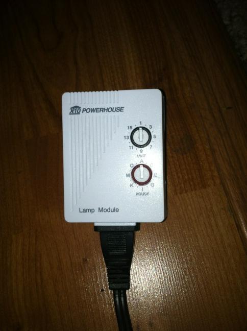
- x10 Lamp Module
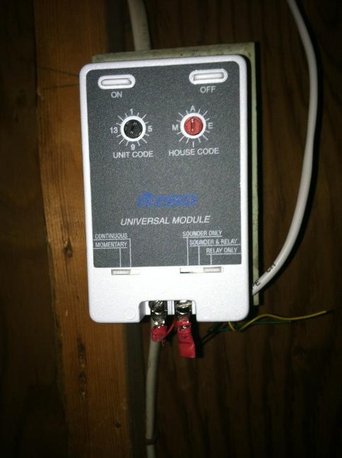
- x10 Universal Relay Module
- RJ11 Cable
- RJ11 Jack
- A LAMP server with an open USB port
Step 1: Building and Configuring the Arduino
Follow the wiring schematics below for wiring your Arduino to an RJ11 Jack.
Data Pin = Pin 8
Zero Crossing Pin = Pin 9
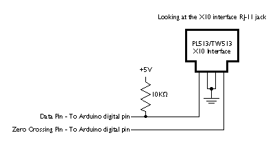
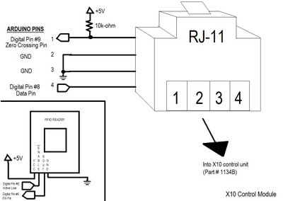
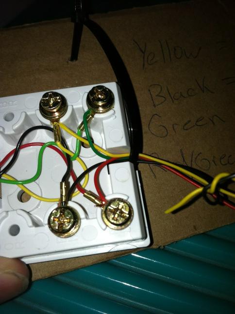
First, wire the 5v connection on the Arduino to the 10KΩ resistor. This will be wired to the data pin 8. Second wire data pin 8 to the black wire on the RJ 11 surface jack. Wire the green and red wires on the RJ11 surface jack together and wire them to the ground pin on the Arduino. Finally wire the data pin 9 to the yellow wire on the surface jack (sometimes you may have to swap the data pin and the zero crossing pin depending on if the RJ11 cord is a cross over or not)
Grab the x10 Library from arduino.
Clone my github repository https://github.com/jfurcean/House-Control.git.
Push the arduino/x10House.pde to the arduino. This code reads data in the form of ascii characters over the USB. It converts the characters into x10 byte codes that are used with the x10 Library. It then uses the x10 Library to push x10 commands out to the PSC04 moudle over RJ11.
Step 2: Configuring the Webserver
A webserver running PHP with an open USB port is required. I used a LAMP server running Ubuntu 11.04. Drop the contents of www from my github repository into your active web directory. Inside index.php you must set $serialPath to the path that your arduino is connected to. For example
$serialPath = “/dev/ttyUSB0″;
If your using Apache as your webserver you must allow Apache to write to that path name.
sudo chgrp www-data /dev/ttyUSB0
sudo chmod 775 /dev/ttyUSB0
The web application reads config files to display certain x10 actions. When viewing the web application you need to make sure userName set. For example:
http://192.168.1.101?userName=john.
This will then use john.xml as the config file. The config file determines what stuff you can control.
<modules>
<module name=’Living Room’ house=’a’ unit=’1′ type=’light’/>
<module name=’Bed Room’ house=’a’ unit=’3′ type=’light’/>
<module name=’Garage’ house=’a’ unit=’2′ type=’button’/>
</modules>
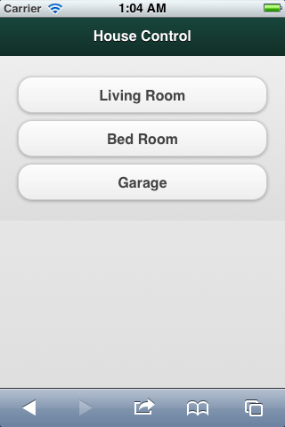
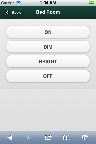
Web Interface
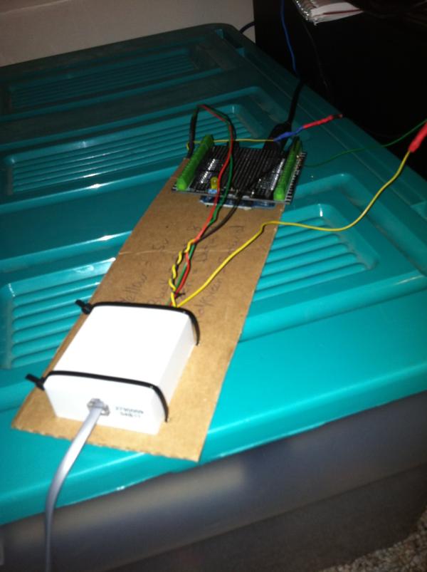
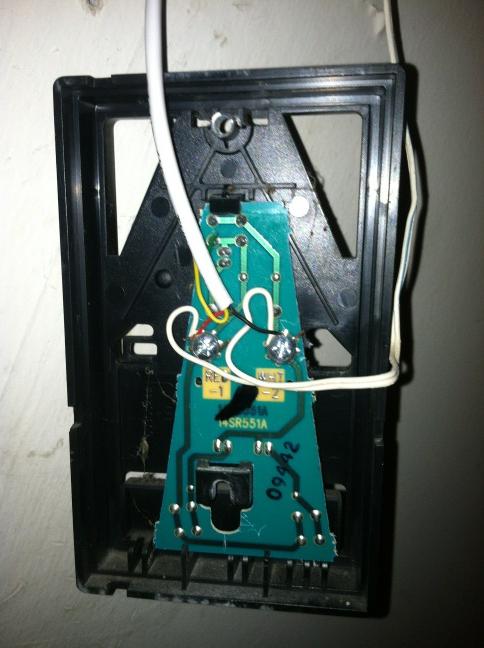
Step 3: Add/Wire x10 Modules
All that is left is to plug any lamp into a lamp module, an appliance into an appliance module or wire a garage door, sprinkler, etc to the universal relay module.
Step 4: Enjoy
Enjoy being able to control your house from any internet capable device connected to your network
Light Control via iPod Touch
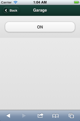
Garage Door Control via iPod Touch
Questions? Comments? Suggestions?
Please feel free to contact me